Difference between revisions of "Digital Electronics (USIU)"
| (3 intermediate revisions by the same user not shown) | |||
| Line 5: | Line 5: | ||
====== In-Lab Exercise 1: Realizing a AND gate ====== | ====== In-Lab Exercise 1: Realizing a AND gate ====== | ||
| − | *'''Step 1 Connect the Circuit as shown in the image below | + | *'''Step 1 Connect the Circuit as shown in the image below''' |
| − | [[File:Lab1-1.png]] | + | [[File:Lab1-1.png|RTENOTITLE]] |
*'''Step 2''' load the python code into your favorite code editor and copy paste the following code and save it as buttonpressed.py | *'''Step 2''' load the python code into your favorite code editor and copy paste the following code and save it as buttonpressed.py | ||
| Line 41: | Line 41: | ||
*'''Step 1''' Connect the Circuit as shown in the image below | *'''Step 1''' Connect the Circuit as shown in the image below | ||
| − | [[File:Lab1-2.png]] | + | [[File:Lab1-2.png|RTENOTITLE]] |
*'''Step 2''' load the python code into your favorite code editor and copy paste the following code and save it as LightsOn.py | *'''Step 2''' load the python code into your favorite code editor and copy paste the following code and save it as LightsOn.py | ||
| Line 68: | Line 68: | ||
''time.sleep(0.05)'' | ''time.sleep(0.05)'' | ||
| − | + | ||
====== In-Lab Exercise 3: Realizing a NOT gate ====== | ====== In-Lab Exercise 3: Realizing a NOT gate ====== | ||
| Line 74: | Line 74: | ||
*'''Step 1''' Connect the Circuit as shown in the image below | *'''Step 1''' Connect the Circuit as shown in the image below | ||
| − | [[File:Lab1-3.png]] | + | [[File:Lab1-3.png|RTENOTITLE]] |
*'''Step 2''' load the python code into your favorite code editor and copy paste the following code and save it as SwitchLightsOn.py | *'''Step 2''' load the python code into your favorite code editor and copy paste the following code and save it as SwitchLightsOn.py | ||
| Line 111: | Line 111: | ||
'' time.sleep(0.05)'' | '' time.sleep(0.05)'' | ||
| − | In-Lab Experiment 1: Realizing AND gate ====== | + | |
| + | |||
| + | |||
| + | ====== In-Lab Experiment 1: Realizing AND gate ====== | ||
'''<u>Wire up the circuit as shown in Figure</u>''' | '''<u>Wire up the circuit as shown in Figure</u>''' | ||
| − | + | ||
#'''Edit the Program shown in the following (python) code below'''<br/>'''(Note: In python the spacing/indentation of the code is important to the code)''' | #'''Edit the Program shown in the following (python) code below'''<br/>'''(Note: In python the spacing/indentation of the code is important to the code)''' | ||
| − | [[File:Lab1-4.png]] | + | [[File:Lab1-4.png|RTENOTITLE]] |
''import RPi.GPIO as GPIO<br/>import time<br/>GPIO.setmode(GPIO.BCM)<br/>GPIO.setup(6, GPIO.IN, pull_up_down = GPIO.PUD_UP)'' | ''import RPi.GPIO as GPIO<br/>import time<br/>GPIO.setmode(GPIO.BCM)<br/>GPIO.setup(6, GPIO.IN, pull_up_down = GPIO.PUD_UP)'' | ||
| Line 177: | Line 180: | ||
#'''Run the Program and Observe LED when''' | #'''Run the Program and Observe LED when''' | ||
| − | '''Switch A is pressed''' | + | *'''Switch A is pressed''' |
| − | + | *'''Switch B is pressed''' | |
| − | '''Switch B is pressed''' | + | *'''When Both Switch A and B are pressed''' |
| − | + | *'''Both Switches A and B are processed simultaneous''' | |
| − | '''When Both Switch A and B are pressed''' | ||
| − | |||
| − | '''Both Switches A and B are processed simultaneous | ||
| − | |||
Latest revision as of 22:18, 28 July 2015
Contents
Digital Electronics
Study of Logic Gates – AND, OR, NOT
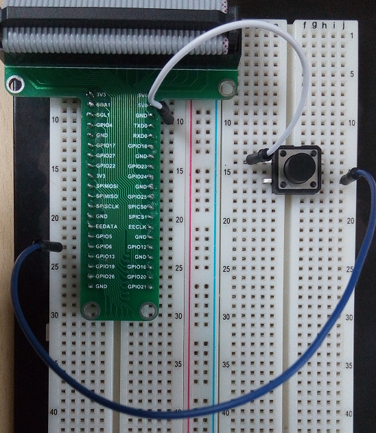
In-Lab Exercise 1: Realizing a AND gate
- Step 1 Connect the Circuit as shown in the image below
- Step 2 load the python code into your favorite code editor and copy paste the following code and save it as buttonpressed.py
In our case we used the command line and opened the nano editor and added the following code
#nano buttonpressed.py
import RPi.GPIO as GPIO
import time
#import random
GPIO.setmode(GPIO.BCM)
GPIO.setup(6,GPIO.IN,pull_up_down = GPIO.PUD_UP)
while True:
input = GPIO.input(6)
if input == False:
print ("Button Pressed")
time.sleep(0.2)
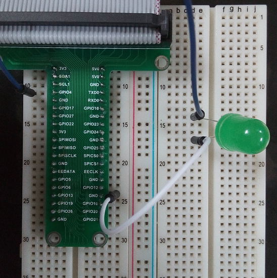
In-Lab Exercise 2: Realizing a OR gate
- Step 1 Connect the Circuit as shown in the image below
- Step 2 load the python code into your favorite code editor and copy paste the following code and save it as LightsOn.py
- In our case we used the command line and opened the nano editor and added the following code
#nano LightsOn.py
import RPi.GPIO as GPIO
import time
GPIO.setmode(GPIO.BCM)
GPIO.setwarnings(False)
led = 4
GPIO.setup(led, GPIO.OUT)
GPIO.output(led,1)
time.sleep(0.5)
GPIO.output(led, 0)
time.sleep(0.05)
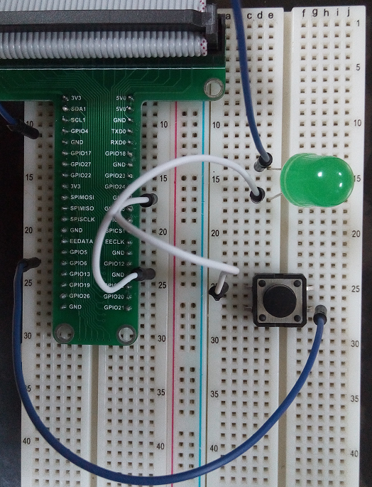
In-Lab Exercise 3: Realizing a NOT gate
- Step 1 Connect the Circuit as shown in the image below
- Step 2 load the python code into your favorite code editor and copy paste the following code and save it as SwitchLightsOn.py
In our case we used the command line and opened the nano editor and added the following code
#nano SwitchLightsOn.py
import RPi.GPIO as GPIO
import time
GPIO.setmode(GPIO.BCM)
GPIO.setup(6,GPIO.IN,pull_up_down = GPIO.PUD_UP)
led = 4
GPIO.setup(led, GPIO.OUT)
while True:
input = GPIO.input(6)
if input == False:
print ("Button Pressed")
time.sleep(0.2)
GPIO.output(led,1)
time.sleep(0.5)
GPIO.output(led, 0)
time.sleep(0.05)
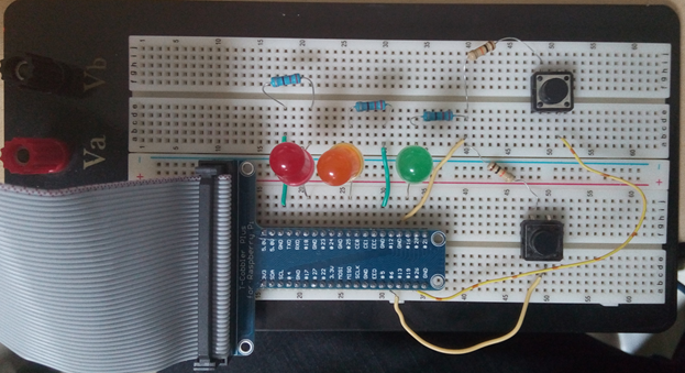
In-Lab Experiment 1: Realizing AND gate
Wire up the circuit as shown in Figure
- Edit the Program shown in the following (python) code below
(Note: In python the spacing/indentation of the code is important to the code)
import RPi.GPIO as GPIO
import time
GPIO.setmode(GPIO.BCM)
GPIO.setup(6, GPIO.IN, pull_up_down = GPIO.PUD_UP)
GPIO.setup(26, GPIO.IN, pull_up_down = GPIO.PUD_UP)
GPIO.setup(16, GPIO.OUT)
a = 0
b = 0
print "\n2 Input AND Gate"
print "\n"
print "A | B | AB"
print "----------"
print "1 | 1 | 1"
print "1 | 0 | 0"
print "0 | 1 | 0"
print "0 | 0 | 0"
print "\n"
while True:
button1 = GPIO.input(6)
button2 = GPIO.input(26)
if button1 == False:
a = 1
if button2 == False:
b = 1
if (a == 1) and (b == 1):
GPIO.output(16, 1)
else:
GPIO.output(16, 0)
time.sleep(1)
a = 0
b = 0
- Run the Program and Observe LED when
- Switch A is pressed
- Switch B is pressed
- When Both Switch A and B are pressed
- Both Switches A and B are processed simultaneous


